Modeling
your own F1 (part 1):
Introduction
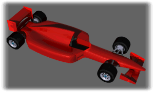
In this Looooonnng tutorial I'll explain how to model
a rather nice formula one racing car using sPatch. Following the different
phases should bring you to a model usable with PovRay. Please note right
now that this model might be tricky to export as a VRML file because of
facet normal problems during export (I intend to write a little HTML page
about these problems so stay tuned!).
Tip: Try to create your profiles with the
same number of points I did or try to think forward to avoid difficult
welding of surves with uneven number of knots.
Important: Model the different parts in
different layers. It will make things easier as you will be able to disable
a finished layer while working on another and will also allow you to export
your model efficiently for render purposes.
Let's get
modeling!
 Phase
1: The air collector .. or whatever
the real name is! Phase
1: The air collector .. or whatever
the real name is!
 |
 |
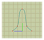
Use add tool  to
draw a profile for the air collector in the YZ plan. to
draw a profile for the air collector in the YZ plan. |
 |
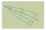
Extrude  that profile three times along the X axis.
 |
 |
Scale  and
translate and
translate  the created profiles
to obtained desired shape. the created profiles
to obtained desired shape. |
 |
Extrude  ,
translate ,
translate  and scale and scale  the
profile at the large end of the shape to give some thickness. the
profile at the large end of the shape to give some thickness. |
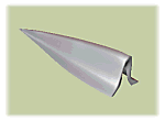 Tip:
To obtain the sharp end, scale down the narrow end until the knots overlap
but do NOT weld them together as this would creat unwanted curves. Tip:
To obtain the sharp end, scale down the narrow end until the knots overlap
but do NOT weld them together as this would creat unwanted curves. |
 Phase
2: The central body ... ahem I'm
not good for names ;-) Phase
2: The central body ... ahem I'm
not good for names ;-)
 |
 |
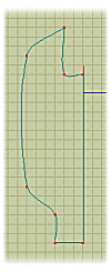
Use add tool  to
draw a profile for half the car body in the XZ plan. to
draw a profile for half the car body in the XZ plan. |
 |
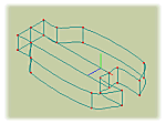
Extrude  that profile along the Y axis.
 |
 |
Make a copy  of
the obtained surface. Flip that copy along Z. of
the obtained surface. Flip that copy along Z. |
 |
Translate  the flipped copy along Z until the central surfaces overlap.
 |
 |
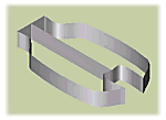
Join the two surfaces together by welding (left click
to grab a knot then still holding right button, right click on the knot
you want to weld on) each of their corners. |
Note: Flipping a surface under sPatch will
invert the orientation of facet normal when exporting the model into VRML
or DXF files. |
 |
 Phase
3: Combining the first two elements. Phase
3: Combining the first two elements.
 |
 |
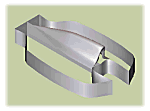
Select  the air collector and place
  it at the desire position, on top of the central body.
 |
 |
Use add tool  to
create segments to be used for joining the two objects. to
create segments to be used for joining the two objects. |
 |
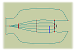
Weld created segments to the air collector on one end
and to the central body on the other as show on the right. |
 |
Use smooth tool  to
solve problems occuring when welding the rear end of the air collector. to
solve problems occuring when welding the rear end of the air collector. |
|

 |
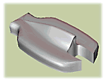 Note:
welding the two objects together creates the missing patches and acheives
a seamless connection with curve continuity. The back of this part, where
the air collector meets the main body can be a bit troublesome when trying
to create the missing patches. Don't lose your calm, proceed with caution
and use the Undo function if it goes wrong. Note:
welding the two objects together creates the missing patches and acheives
a seamless connection with curve continuity. The back of this part, where
the air collector meets the main body can be a bit troublesome when trying
to create the missing patches. Don't lose your calm, proceed with caution
and use the Undo function if it goes wrong.
 Phase
4: The nose. Phase
4: The nose.
 |
 |
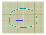
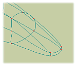
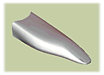
Use add tool  to draw a profile for the nose in the YZ plan.
 |
 |
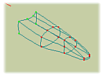
Extrude  that
profile three times along the X axis. that
profile three times along the X axis. |
 |
Scale  and
translate and
translate  the created profiles
to obtain the desired shape. the created profiles
to obtain the desired shape. |
 |
Use add tool  to draw a curve segment. Weld this segment horizontally between the two
middle knots.
 |
 |
Weld the top two knots to the middle two knots to seamlessly
close the tip of the nose and create the diving effect. |
|
 |
 Phase
5: Combining the nose with the rest. Phase
5: Combining the nose with the rest.
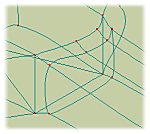 |
 |
Move  the
nose part in place in front of the main body. the
nose part in place in front of the main body. |
 |
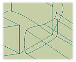
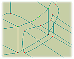
Use the add tool  to create a 4 points curve (don't connect it to anything yet).
 |
 |
Place that curve at the front of the main body, facing
the top of the nose part. |
 |
Weld the two extremities of that curve to the sides of
the cockpit. If you encounter curve problems, use the peak tool  on
the two extrimities once connected to the cockpit. on
the two extrimities once connected to the cockpit. |
 |
Create simple segments with the add tool  then use these segments to connect the knots facing eachother.
 |
 |
Use another couple of segment to close the bottom of
the cockpit. |
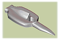 Note:
This part is one of the most tricky phase of this tutorial. Welding these
two objects together this way creates curve problems as sPatch tries to
connect the different curves to form one. By following these instruction
you should reach an acceptable result. however, since the creation of this
model I found out a way of doing this more efficiently and I will explain
it in my next tutorial. Note:
This part is one of the most tricky phase of this tutorial. Welding these
two objects together this way creates curve problems as sPatch tries to
connect the different curves to form one. By following these instruction
you should reach an acceptable result. however, since the creation of this
model I found out a way of doing this more efficiently and I will explain
it in my next tutorial. |

Proceed
to part 2
|

![]() Phase
1: The air collector .. or whatever
the real name is!
Phase
1: The air collector .. or whatever
the real name is!


 Tip:
To obtain the sharp end, scale down the narrow end until the knots overlap
but do NOT weld them together as this would creat unwanted curves.


 Note:
welding the two objects together creates the missing patches and acheives
a seamless connection with curve continuity. The back of this part, where
the air collector meets the main body can be a bit troublesome when trying
to create the missing patches. Don't lose your calm, proceed with caution
and use the Undo function if it goes wrong.
![]() Phase
4: The nose.
Phase
4: The nose.


 Note:
This part is one of the most tricky phase of this tutorial. Welding these
two objects together this way creates curve problems as sPatch tries to
connect the different curves to form one. By following these instruction
you should reach an acceptable result. however, since the creation of this
model I found out a way of doing this more efficiently and I will explain
it in my next tutorial.